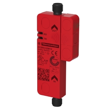
XCSRC32M12
Preventa RFID safety switch, Telemecanique Safety switches XCS, contactless Daisy Chain model, 2 new re pairing enabled

Commercialized

Expand all
Datasheet
Range of product
Telemecanique Safety switches XCS
Product or component type
Preventa RFID safety switch
Component name
XCSRC
Design
Rectangular, standard
Size
Transponder: 50 x 15 x 15 mm
Reader: 119.6 x 30 x 15 mm
Reader: 119.6 x 30 x 15 mm
Material
Valox
Electrical connection
2 male connectors
Connector type
M12 male
Type of output stage
Solid-state, PNP
Safety outputs
2 NO
Number of poles
5
Local signalling
Green, orange and red 2 multi-colour LEDs
[Sa] assured operating distance
10 mm face to face
[Sar] assured tripping distance
35 mm face to face
Approach directions
3 directions-transponder with rotary sensing face
[Ue] rated operational voltage
24 V DC (- 20...10 %)SELV or PELV conforming to IEC 60204-1
[Ie] rated operational current
60 mA
[Ui] rated insulation voltage
30 V DC
[Uimp] rated impulse withstand voltage
0.8 kV conforming to IEC 60947-5-2
Protection type
Short-circuit protection
Maximum switching voltage
26.4 V DC
Switching capacity in mA
200 mA
Switching frequency
<= 0.5 Hz
Maximum discordance time
120 ms + 18 ms per additional switch connected in series
Response time
120 ms + 50 ms typical per additional switch connected in series
Maximum delay first up
5 s
Tightening torque
< 1.5 N.m
Standards
IEC 60947-5-2
IEC 60947-5-3
ISO 14119
IEC 60947-5-3
ISO 14119
Product certifications
CSA 22-2
FCC
IC
RCM
Ecolab
TÜV
E2
FCC
IC
RCM
Ecolab
TÜV
E2
Marking
CULus
TÜV
IC
CE
FCC
RCM
EAC
TÜV
IC
CE
FCC
RCM
EAC
Safety level
SIL 3 conforming to IEC 61508
SILCL 3 conforming to IEC 62061
PL = e conforming to ISO 13849-1
Category 4 conforming to ISO 13849-1
SILCL 3 conforming to IEC 62061
PL = e conforming to ISO 13849-1
Category 4 conforming to ISO 13849-1
Safety reliability data
PFHD = 5E-10/h conforming to IEC 62061
PFHD = 5E-10/h conforming to ISO 13849-1
PFHD = 5E-10/h conforming to ISO 13849-1
Service life
20 year(s)
Ambient air temperature for operation
-25…70 °C
Ambient air temperature for storage
-40…85 °C
Vibration resistance
10 gn (f= 10…150 Hz) conforming to IEC 60068-2-6
Shock resistance
30 gn for 11 ms conforming to IEC 60068-2-27
Electrical shock protection class
Class III conforming to IEC 61140
IP degree of protection
IP65 conforming to IEC 60529
IP66 conforming to IEC 60529
IP67 conforming to IEC 60529
IP69K conforming to DIN 40050
IP66 conforming to IEC 60529
IP67 conforming to IEC 60529
IP69K conforming to DIN 40050
Unit Type of Package 1
PCE
Number of Units in Package 1
1
Package 1 Height
3.3 cm
Package 1 Width
14.8 cm
Package 1 Length
17.5 cm
Package 1 Weight
106.0 g
Unit Type of Package 2
S01
Number of Units in Package 2
12
Package 2 Height
15.0 cm
Package 2 Width
15.0 cm
Package 2 Length
40.0 cm
Package 2 Weight
1.447 kg
Sustainable offer status
Green Premium product
REACh Regulation
EU RoHS Directive
Pro-active compliance (Product out of EU RoHS legal scope)
Mercury free
Yes
RoHS exemption information
Circularity Profile
No need of specific recycling operations
California proposition 65
WARNING: This product can expose you to chemicals including: Diisononyl phthalate (DINP), which is known to the State of California to cause cancer, and Di-isodecyl phthalate (DIDP), which is known to the State of California to cause birth defects or other reproductive harm. For more information go to www.P65Warnings.ca.gov
Expand all
Technical Drawings
Dimensions
Connections
M12 Connectors, 5-pin
- (1) + 24 VDC
- (2) OSSD2 (O2)
- (3) 0 VDC
- (4) OSSD1 (O1)
- (5) Diagnosis Out (Do)
M12 Connectors, 5-pin
- (1) + 24 VDC
- (2) OSSD2 (O2)
- (3) 0 VDC
- (4) OSSD1 (O1)
- (5) Diagnosis Out (Do)
- (1) + 24 VDC
- (2) INPUT 2 (I2)
- (3) 0 VDC
- (4) INPUT 1 (I1)
- (5) Diagnosis In (Di)
Connections
Wiring Diagram: Series Connection
- (1) Start
- (2) Power circuit
- (3) Loopback device
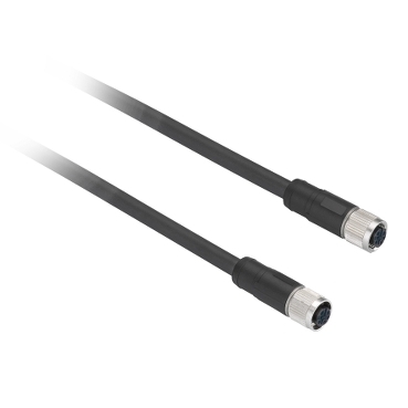
- (4) M12/M12 female jumpers
- (5) Pre-wired female connectors
- (6) Diagnostic module (option)
Cat. 4 / PL=e (EN/ISO 13849-1) / SIL3 (IEC 61508) / SILCL3 IEC 62061), if combined with an appropriate Preventa XPS Safety module PL=e / SIL3
NOTE: KM1 and KM2 contactors must have force-guided contacts.
Mounting and Clearance
Mounting and Clearance
Face to Face Mounting (Preferred Configuration)
- e min. > 2 mm. (e: recommended minimum mounting distance between transponder and reader)
- d : Detection limit
Mounting and Clearance
Side by Side Mounting
- e: Recommended minimum mounting distance between transponder and reader.
Correct Mounting Configuration
Mounting and Clearance
Minimum Mounting Clearances between Safety Switches
| E1 min. | E2 min. | E3 min. |
|---|---|---|
| 45 | 150 | 65 |
| E1 min. | E2 min. | E3 min. |
|---|---|---|
| 1.77 | 5.91 | 2.56 |
Detection Curves
Face to Face Mounting (Preferred Configuration)
- Sar: Assured release distance
- Sao: Assured operating distance
- (1) Recommended minimum mounting distance between transponder and reader.
Sao and Sar sensing distances along Y axis as function of Z (longitudinal misalignment for X=0)
Detection Curves
- Sar: Assured release distance
- Sao: Assured operating distance
- (1) Recommended minimum mounting distance between transponder and reader.
- Sar: Assured release distance
- Sao: Assured operating distance
- (1) Recommended minimum mounting distance between transponder and reader.
Sao and Sar sensing distances along X axis as function of Z (transverse misalignment for Y=0)
Detection Curves
Side by Side Mounting
- Sar: Assured release distance
- Sao: Assured operating distance
- (1) X=0 for X<0
- (2) X=0 for X>0
- (3) Recommended minimum mounting distance between transponder and reader.
Sao and Sar sensing distances along Y axis as function of X (longitudinal misalignment for Z=0mm)
Detection Curves
- Sar: Assured release distance
- Sao: Assured operating distance
- (1) X=0 for X<0
- (2) X=0 for X>0
- (3) Recommended minimum mounting distance between transponder and reader.
- Sar: Assured release distance
- Sao: Assured operating distance
- (1) X=0 for X<0
- (2) X=0 for X>0
- (3) Recommended minimum mounting distance between transponder and reader.
Sao and Sar sensing distances along Z axis as function of X (transverse misalignment for Y=0mm)
Expand all
Documents & Downloads
Document name
Date
Size
Document name
Date
Size
11/23/2023
8.8 MB
Document name
Date
Size
11/23/2023
3.0 MB
Document name
Date
Size
11/23/2023
12.4 MB
11/23/2023
12.4 MB
11/29/2023
23.6 MB
11/29/2023
23.5 MB
Document name
Date
Size
Document name
Date
Size
11/23/2023
195.3 kB
11/29/2023
195.3 kB
Expand all
Related products & accessoires
XCSRK2A3
Telemecanique Safety switches XCS, Blank RFID Transducer for XCSRC3xxx
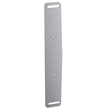
XCSRZSTK1
Telemecanique Safety switches XCS, Steel fixing plate for RFID Transducer XCSRK2A*
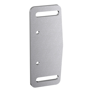
XCSRZSRC1
Telemecanique Safety switches XCS, Steel fixing plate for RFID Reader XCSRC**
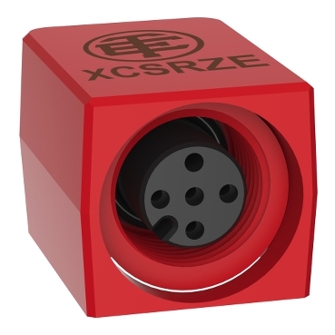
XCSRZE
M12 plug for XCSRC Daisy Chain models, Telemecanique Safety switches XCS, Loopback device
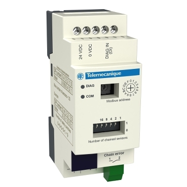
XCSRD210MDB
Telemecanique Safety switches XCS, diagnostic module for XCSRC Daisy Chain models, Modbus RTU
XZCR1111064D3
Telemecanique Safety light curtains XUSL, Series connection jumper, 2 straight M12, Female/Female con, 3 m, 5 pins
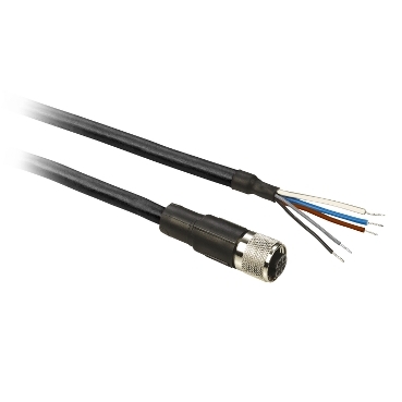
XZCP11V12L2
Pre wired connectors XZ, straight female, M12, 5 pins, cable PUR 2 m
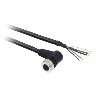
XZCP12V12L2
Pre wired connectors XZ, elbowed female, M12, 5 pins, cable PUR 2 m
Back to top